F2-84 Build Guide
- Plateless kit for F2-84
Hello there! This is the page for the basic assembly instruction of the F2-84 Keyboard. This page will show you what you’ll need to fully assemble your board and the tools you’re going to need along the way.
What’s Inside the Box
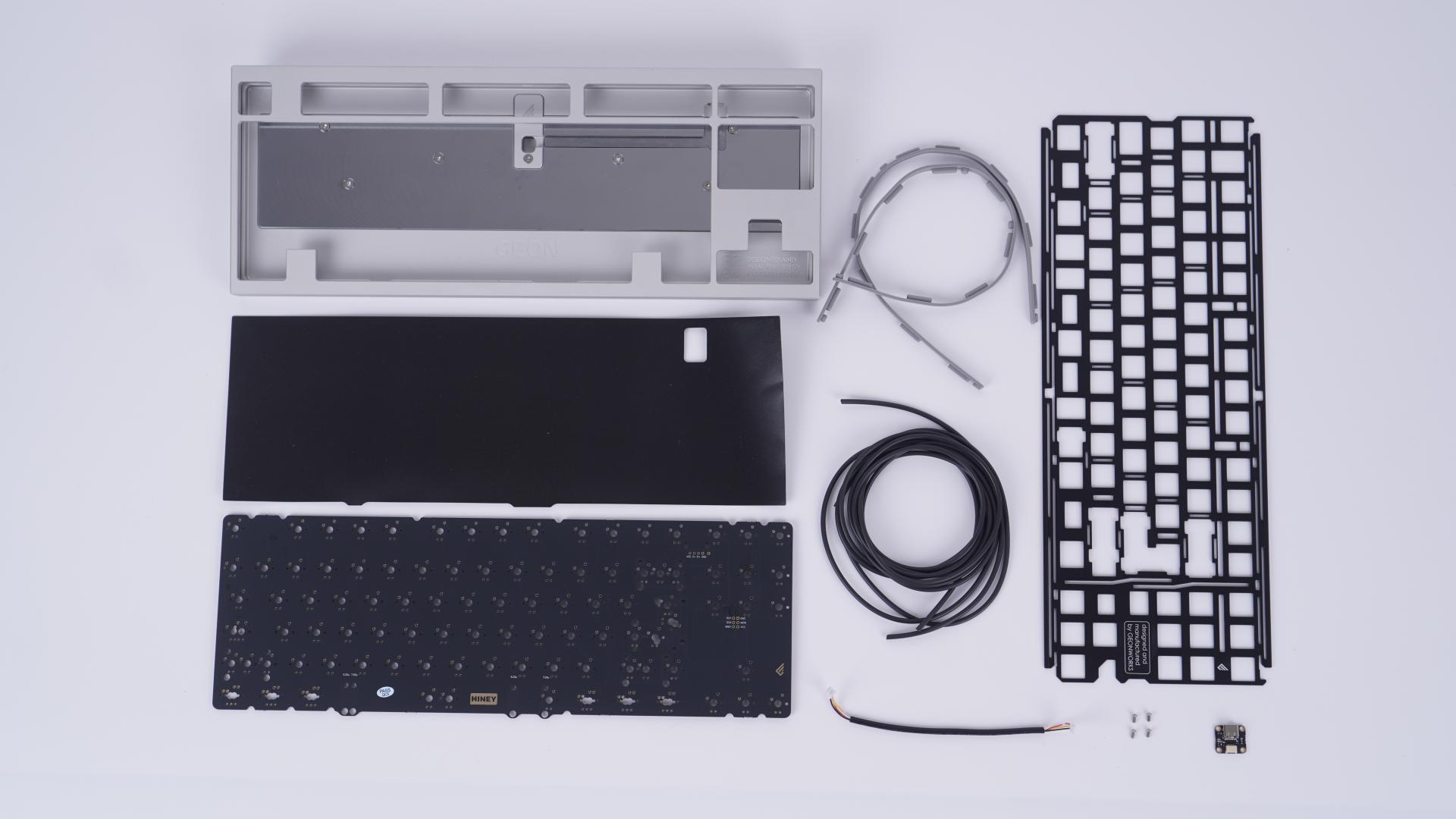
First let’s look inside, what you’ll get in the box
(Starting from the top left corner, listing from top to bottom, moving left to right)
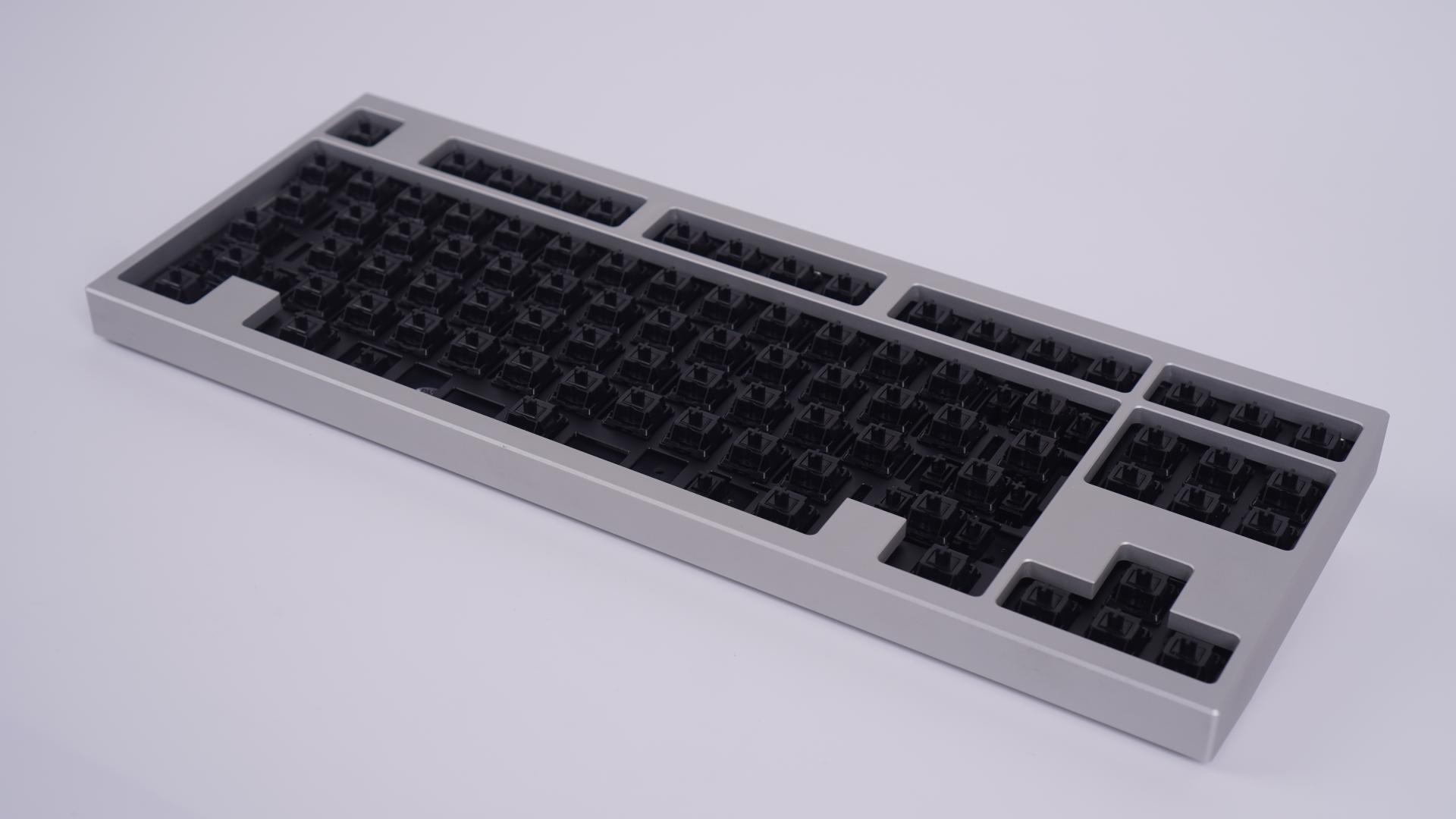
- Partially assembled F2-84 (x1)
- Anti-static internal sheet (x1)
- H-87nu PCB (x1)
- Color matching bump-on feet (a set of 2)
- 2 meters of 2mm thick Viton O-ring gasket (x1)
- JST connector wire (x1)
- Aluminum F2-84 Plate (x1)
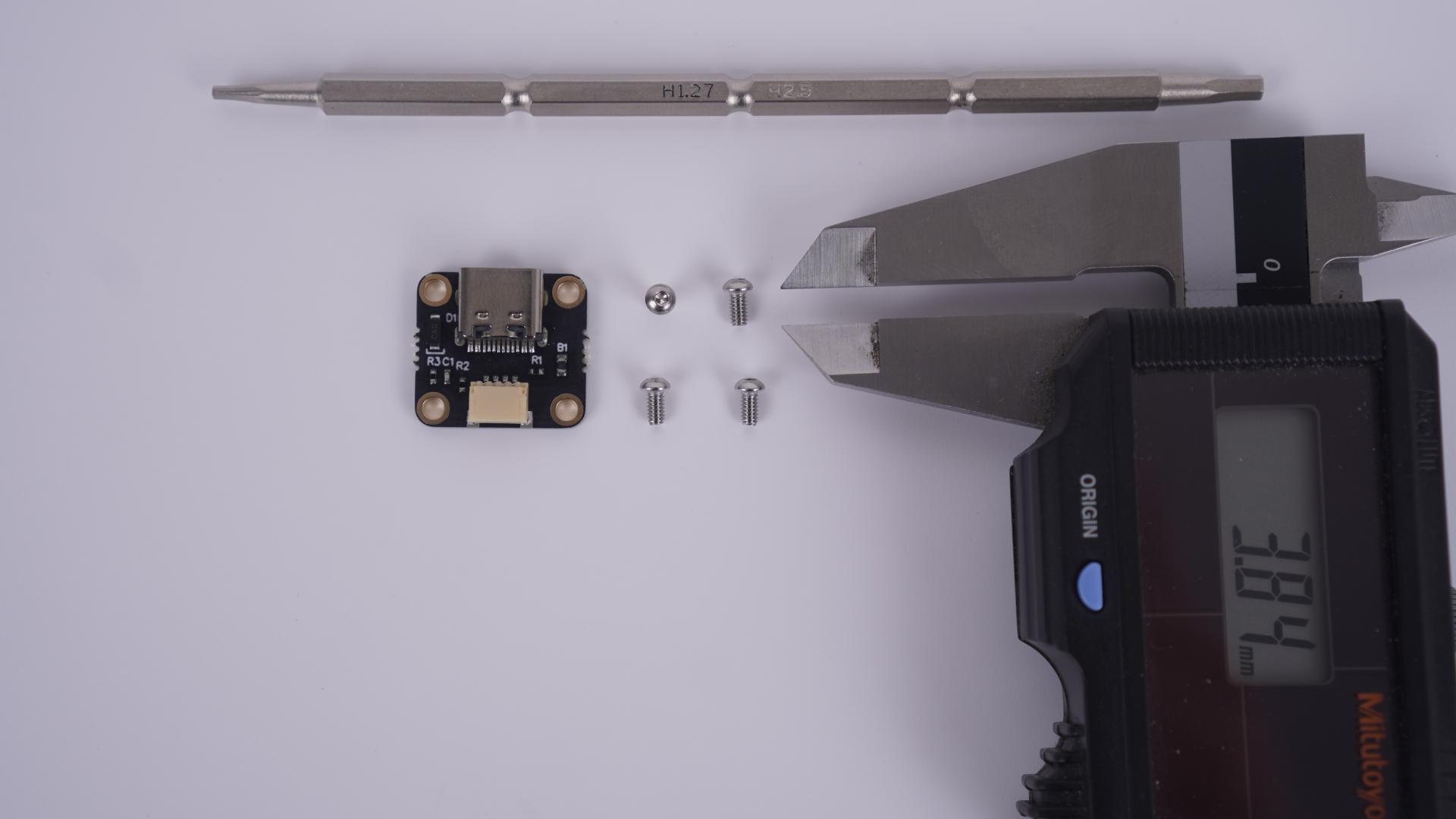
- USB-C Daughterboard (x1)
- Carrying Case (Not displayed) (x1)
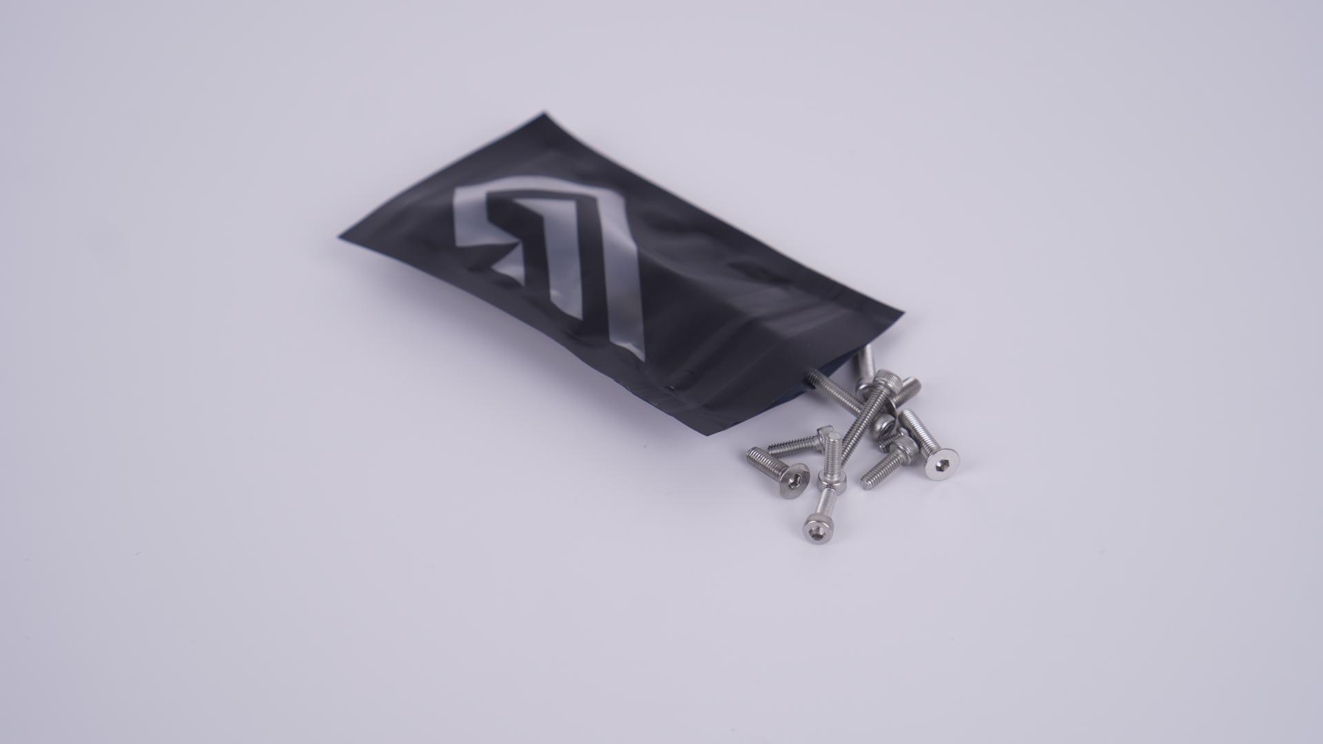
NOTE: In your package, you’ll see that your board has all the screws that it should have on the board itself excluding the daughter-board screws, which you can find inside your extra-screw bag that’s included inside your carrying bag.
What You’ll need for full Assembly
These are items that you’ll need for assembling the F2-84, that are not included in the package and will have to acquire yourselves.
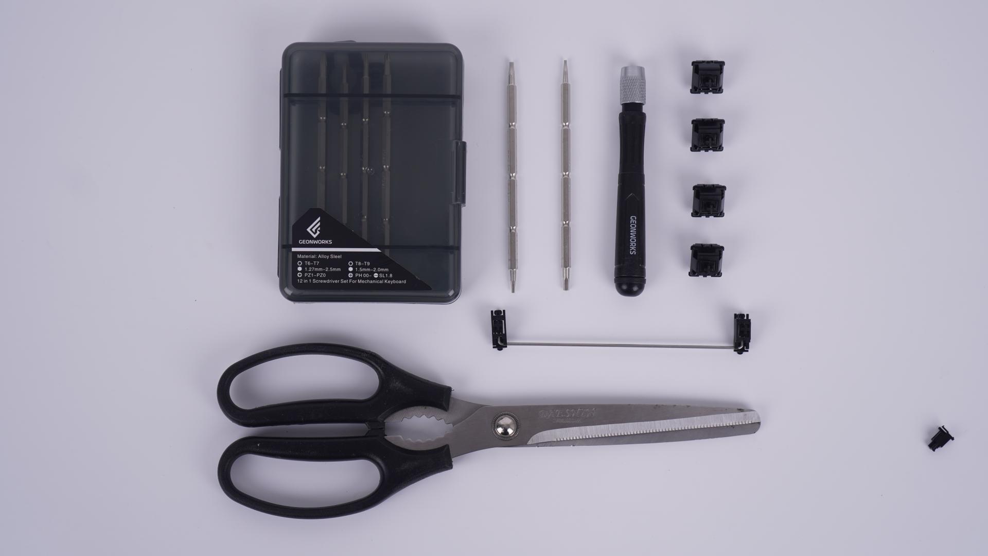
- A pair of scissors (for cutting the Viton O-ring gasket)
- A TKL Stabilizer kit WITH a 7U wire
- A bag of switches of your choice (90 pcs is preferred)
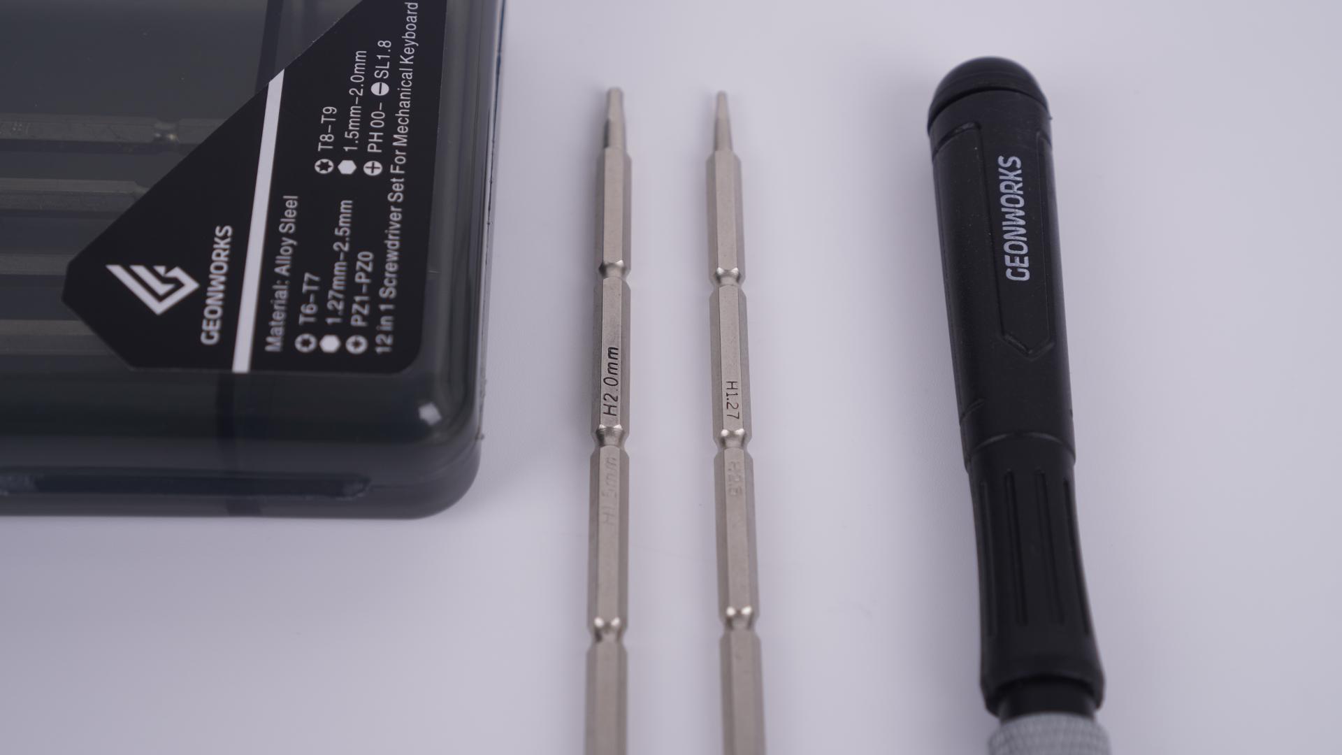
- Hex Screwdrivers: One 2.0 mm Hex, One 1.27 mm Hex
- A set of keycaps with a included 7U spacebar (not displayed)
If you cannot find the Hex screwdrivers or Allen keys that are not matching with this size spec, you can purchase a set of Geonworks screwdrivers set down below
For customer’s in Korea only : link
For international customers : link
Assembly
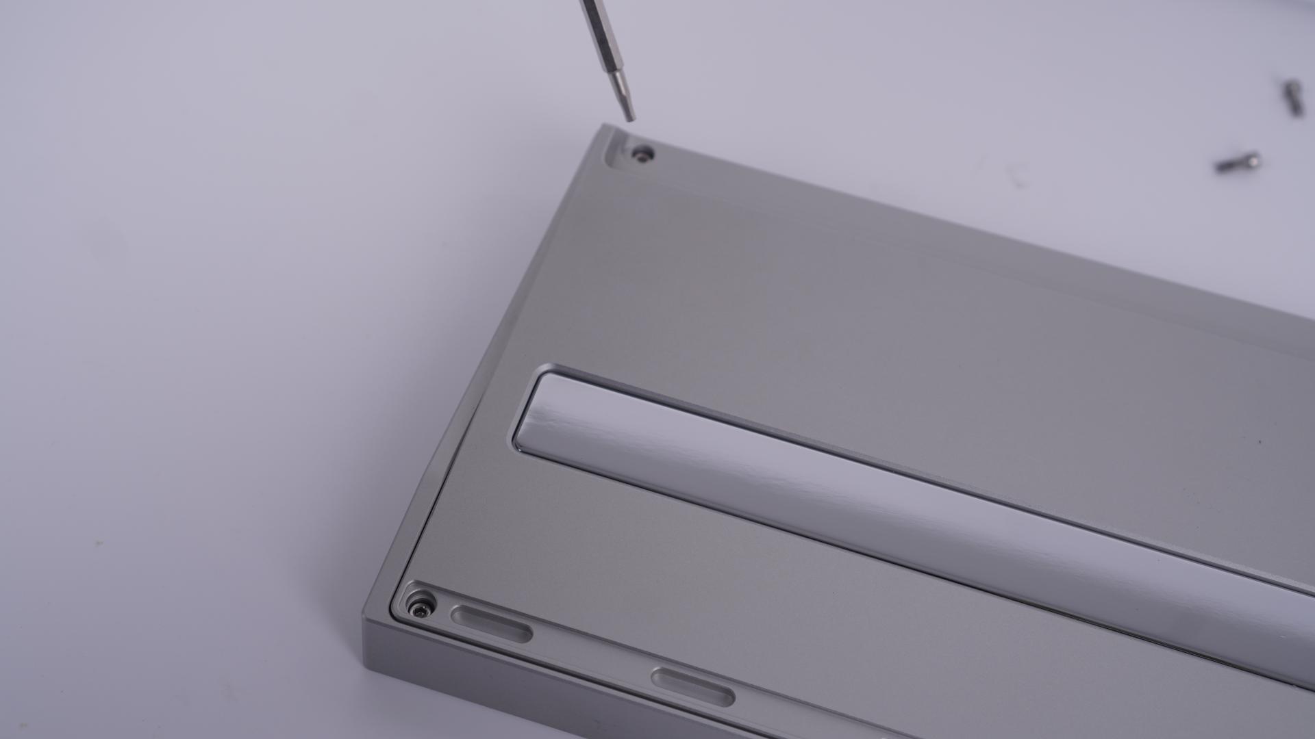
First take your board apart excluding the internal weight, which disassembly isn’t required for the assembly steps.
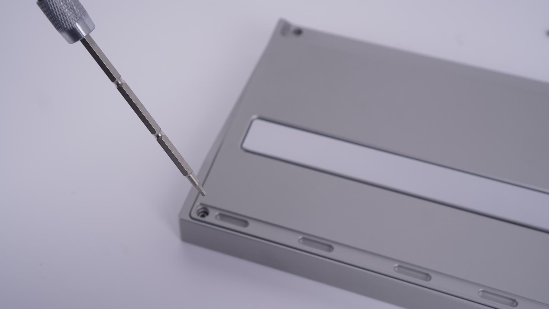
Take out all the 4 outer screws that are on the external weight

Now remove the remaining screws on the board and keep it somewhere visible and safe
Take the top plate off and set it aside, now you’ll need to take the daughter-board holder off with a 2.0 mm hex screwdriver
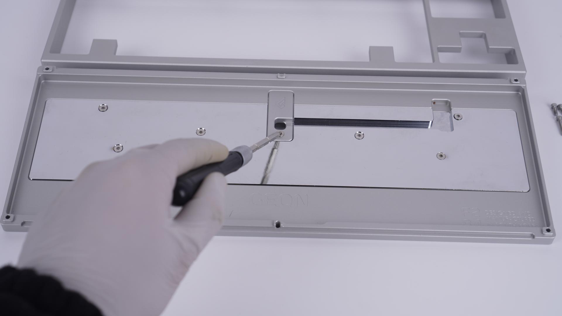
Once that’s removed, take four 4mm dish-head hex screws from your extra screw bag and take a 1.27mm driver, and screw in the daughter-board onto the daughter-board mount.
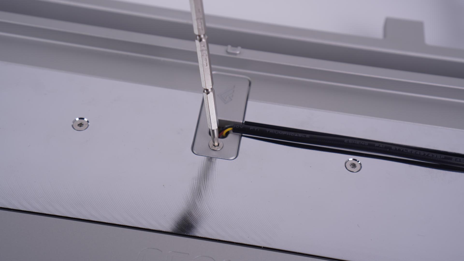
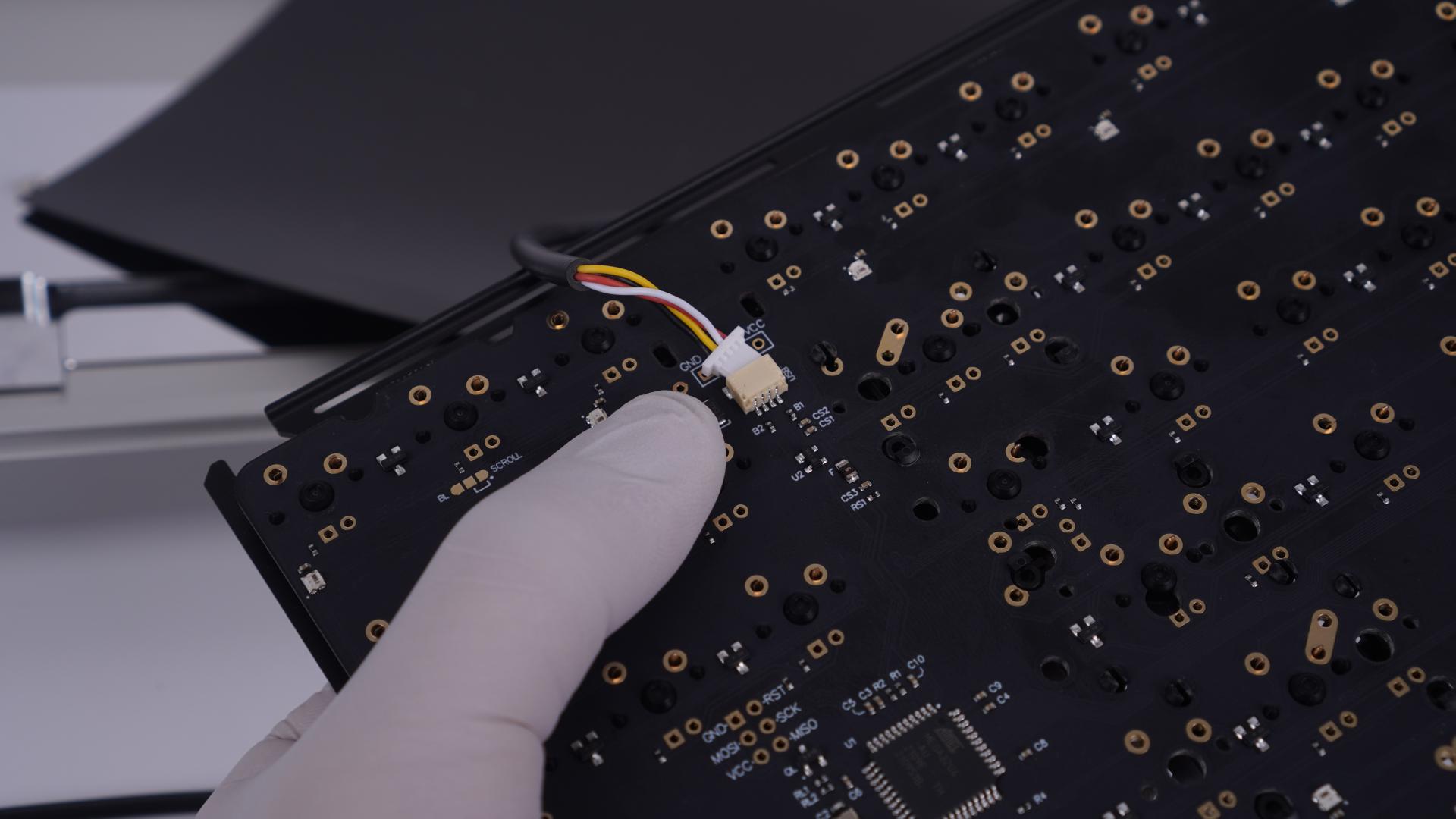
When you’ve done that, connect your JST connector wire to the daughter and route it inside the hole of the mount. And make sure that you connect the correct way. (displayed below)
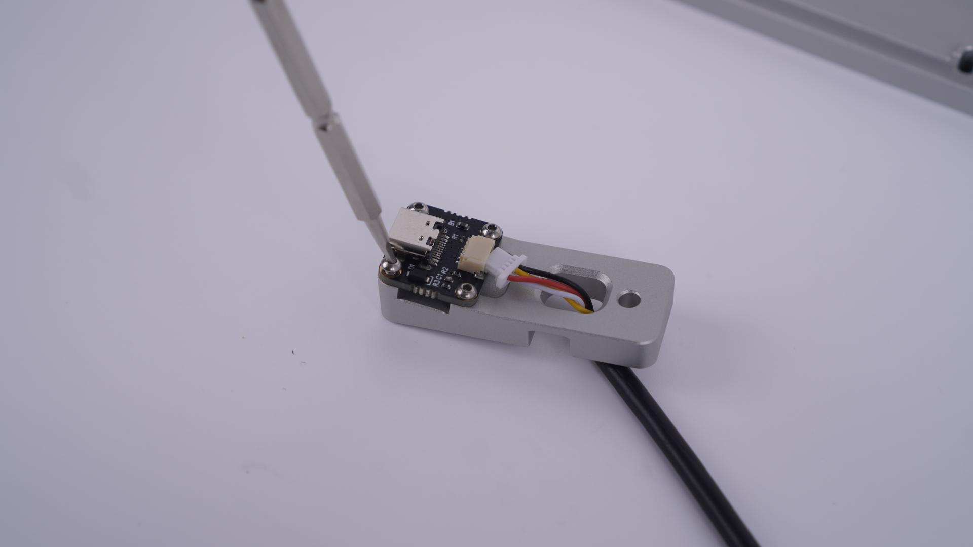
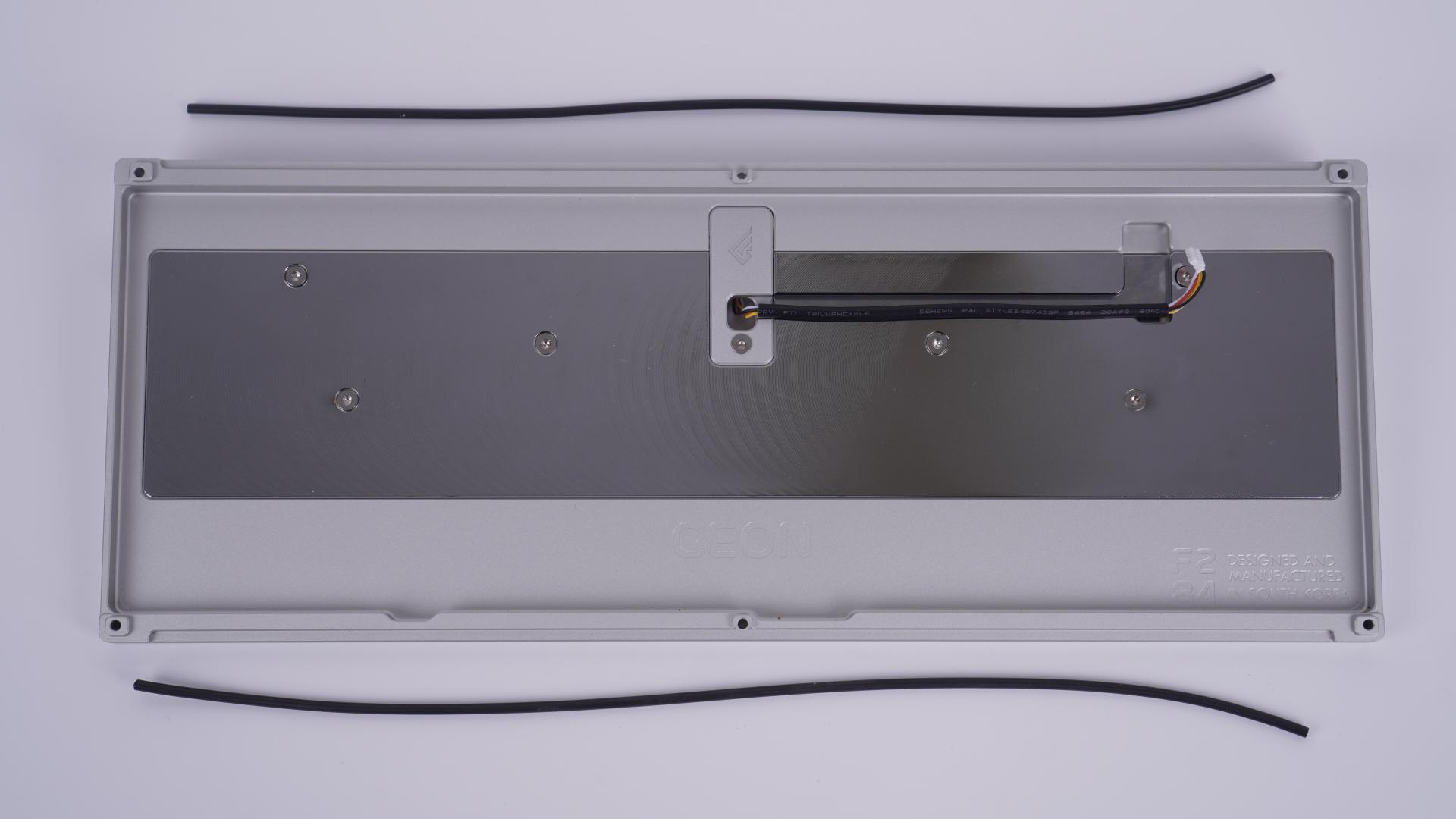
Place the mount on the weight, where the logo shows up in front of you. You can additionally fix the cable on the cable routing crevice with some tape, but this is optional on your part.
Set your bottom plate to the side and let’s move on to the PCB and plate.
NOTE: If you have a set of platelets mount kit for your F2-84
and would prefer using a plate-less keyboard please refer to this page : link
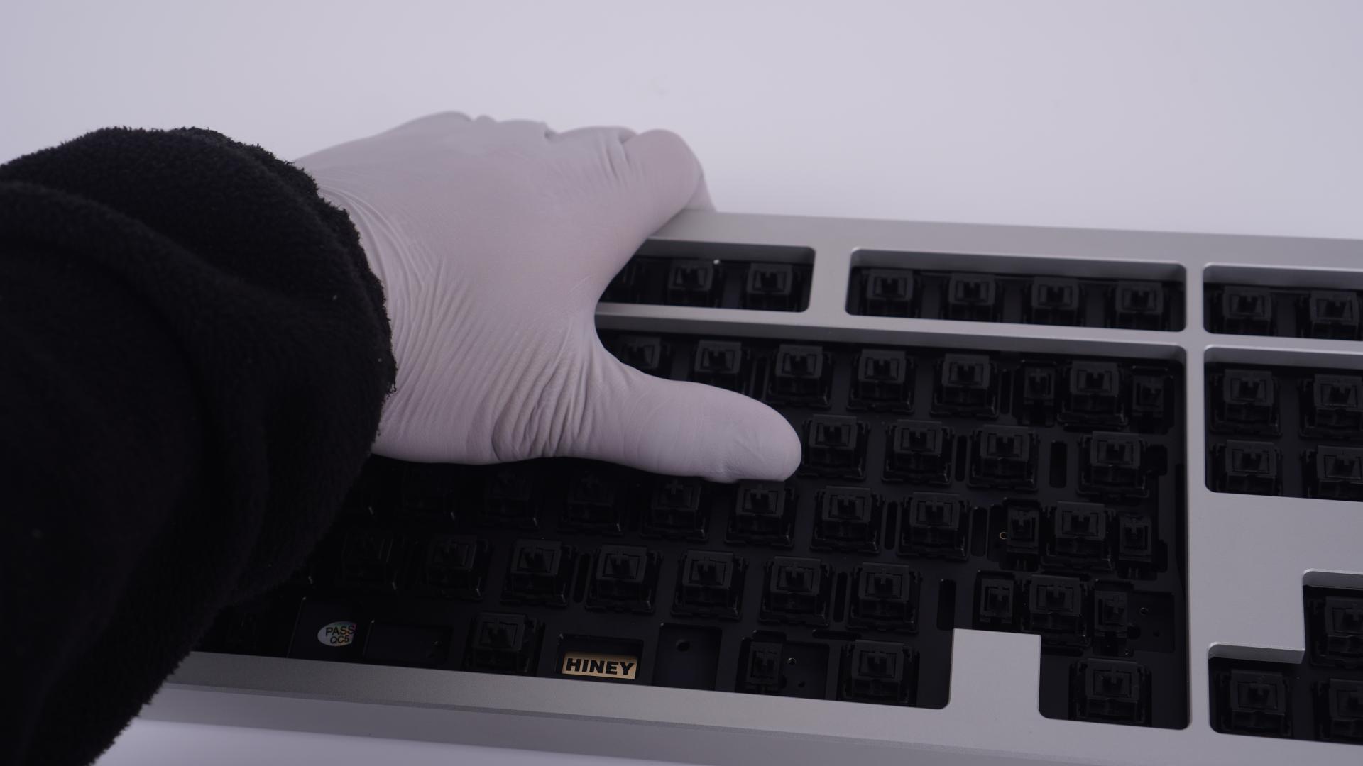
You’ll need a total of 84 switches for your board and a set of TKL stabilizers with a 7U wire that comes included. The switches and the stabilizers are sold separately and you’ll need to provide these two parts yourselves.

Once you’ve assembled your PCB and plate, now you need to bring back the bottom plate of the board.

Take your anti-static sheet and place it inside the bottom plate and route the other end of the JST connector outside of the hole.

And before you fully place down your PCB/Plate assembly, connect your PCB and the JST connector (shown below)
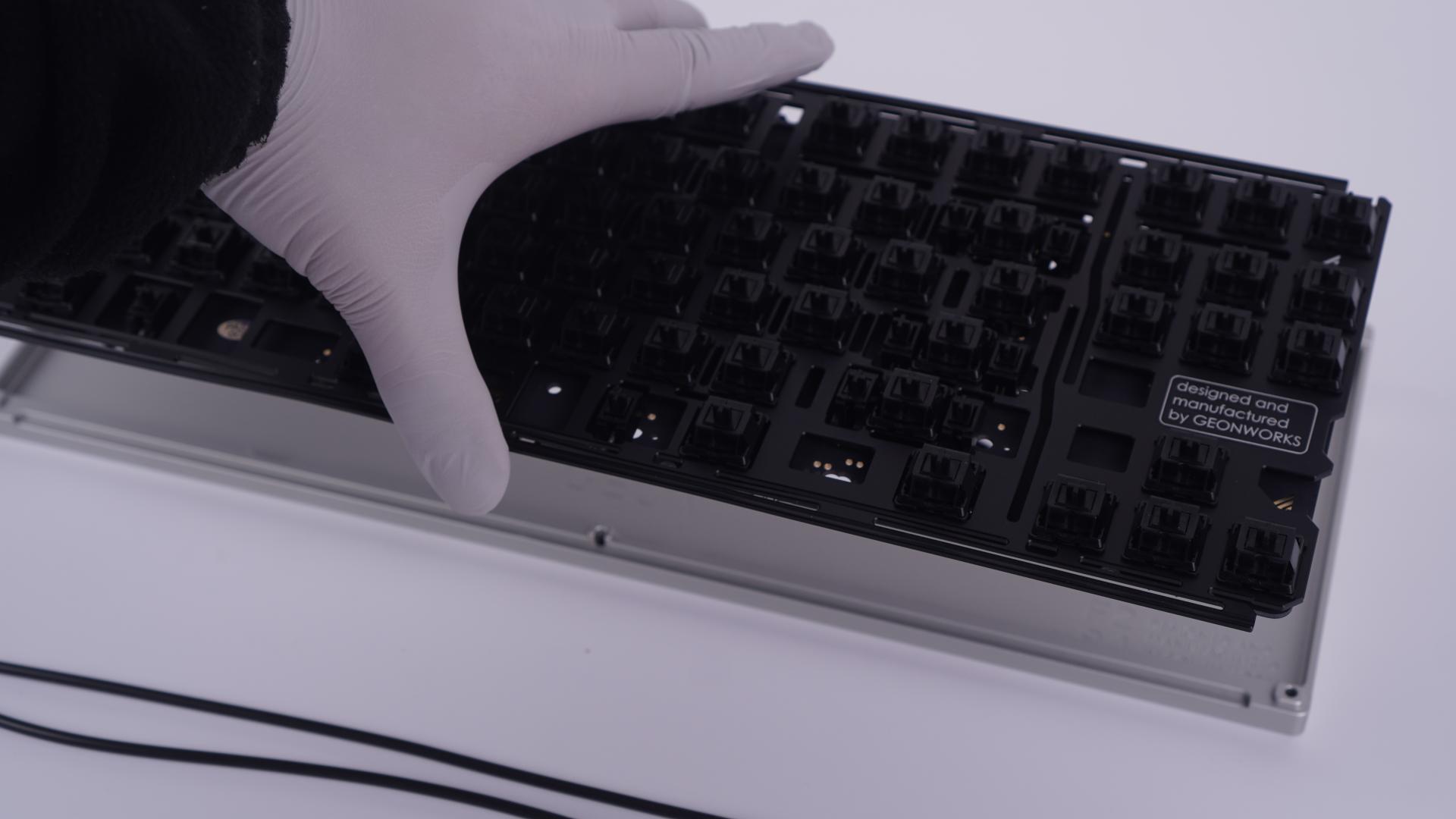
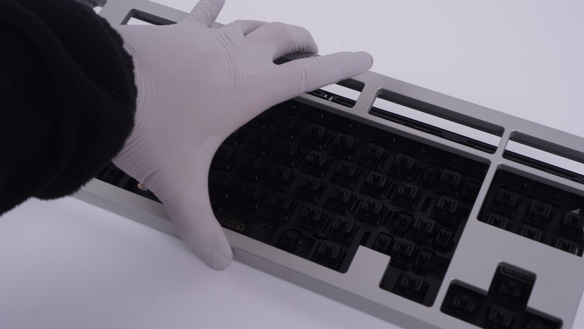
Place your plate on top, and fit it inside the correlating holes.
Now, take your Viton O-ring gasket and a pair of scissors then cut a strip that will fit on the grooves of the top and bottom plate. (An example displayed below)

Take a strip of o-ring and push it inside the grooves of the top plate.

For your bottom plate o-rings, instead of directly placing them onto the grooves, while the plate is still on, take a strip and insert them on the side. This will make things significantly easier since the weight of the plate will hold down the o-rings.

After you’ve placed your top plate onto the bottom plate, you are now ready for the final assembly.
Grab your board from the top, so that you can grab both your top and bottom plate, and flip it upside down.
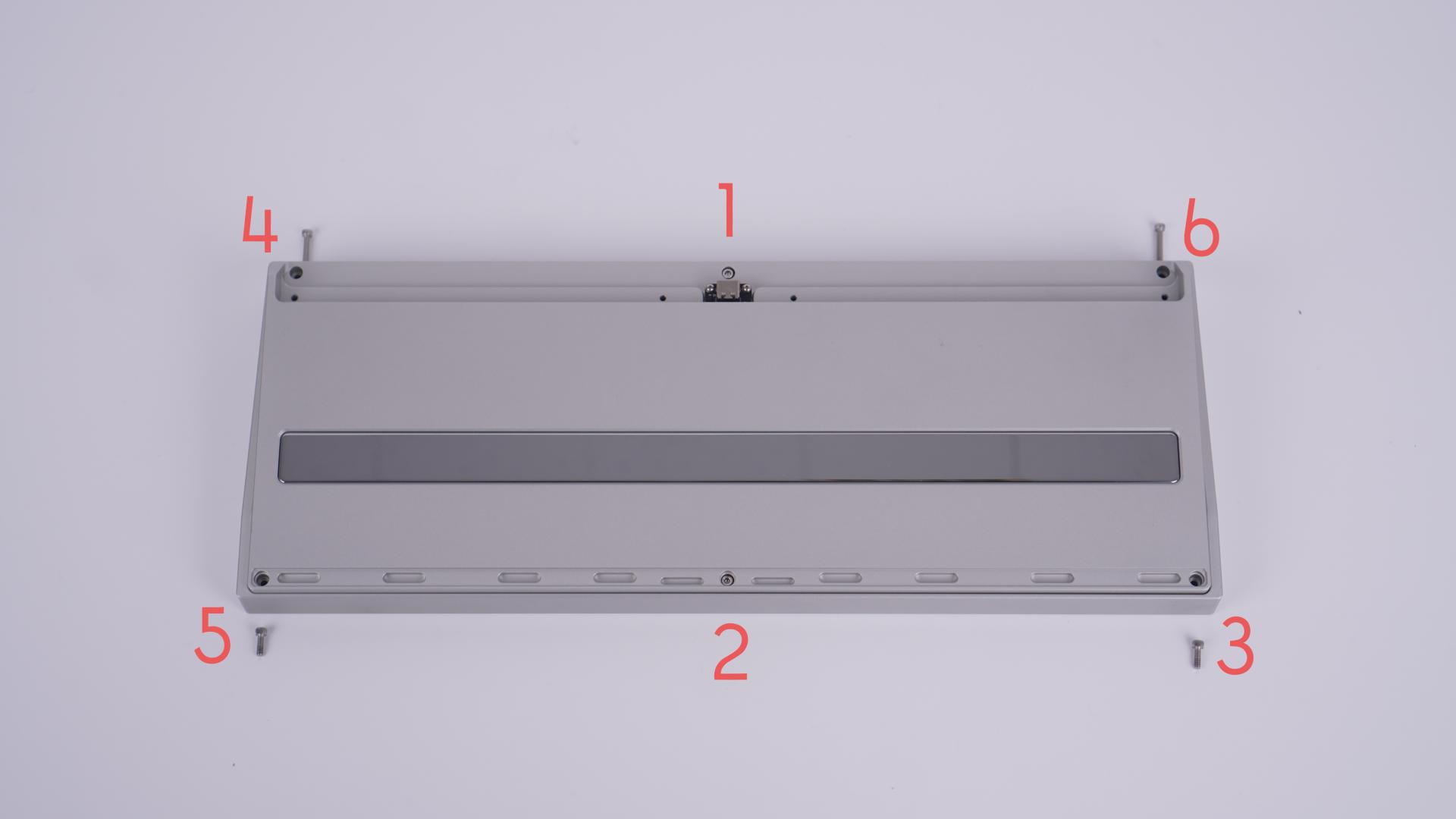
Once you flipped the board on its topside on your table, you will now need to screw in the two middle holes first with your 2.0mm hex driver. This is because the middle hole will evenly distribute the weight and the tightness. After that, you can put the remaining screws on the corners. (The picture below shows the suggested order of operation.)
Top screw measurement: 15 mm Socket head Hex screw

Bottom Screw: 8 mm socket head hex screw

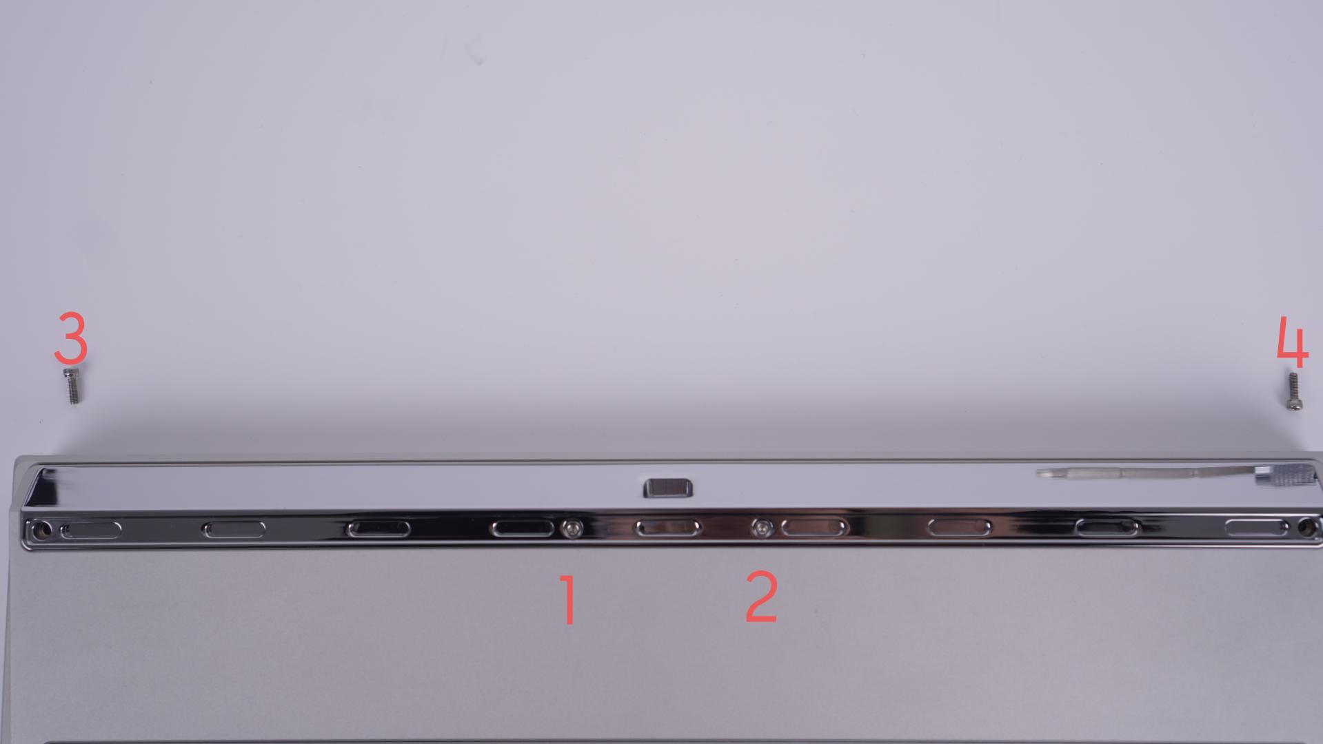
Now for your outer weight, you’ll need to work from the inside out, using your 2 mm hex driver once more.
(please refer to this page : link F2-84 Outer Weight assembly/ Warping Issues page if you have difficulties installing your outer weight.) Your outer weight will be using up the remaining 8 mm socket head screws.
Finally, install your bump-on feet that correlate to the grooves at the bottom of the case. And flip your keyboard around, install your keycaps, and enjoy your assembled board.